Welcome! This manual details the X Pack 7 Drone, offering guidance on operation, safety, and maintenance.
Experience stable flight with its 6-axis gyroscope and altitude hold.
Overview of the X Pack 7 Drone
The X Pack 7 is a cutting-edge quadcopter designed for both aerial photography and recreational flying. Featuring a foldable design and intuitive controls, it’s perfect for enthusiasts of all skill levels. Equipped with a 2.4GHz remote and WiFi app control, users enjoy a 50m RC range and 25m WiFi range.
Its 6-axis gyroscope and altitude hold function ensure stable, high-quality footage. This drone boasts a 2.0MP camera, delivering vibrant images and videos.
Key Features and Specifications
Key features include a foldable design for portability, a 2.0MP camera for stunning visuals, and a robust 6-axis gyroscope for stable flight. The X Pack 7 offers both 2.4GHz remote control and WiFi app connectivity.
Specifications: RC Control (2.4GHz 4ch), WiFi Range (25m), RC Range (50m), Coreless Motors, and dimensions of 91 x 91 x 38 mm. Battery capacity is 920mAh, ensuring extended flight times.

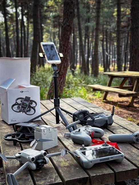
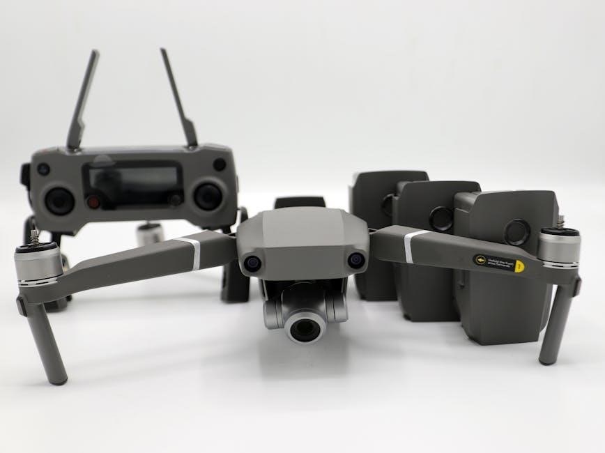
Unboxing and Component Identification
Carefully unpack the drone, remote controller, battery, propellers, and charging system. Verify all components are present before proceeding with setup.
Drone Components List
The X Pack 7 Drone package includes: the drone airframe itself, four coreless motors ensuring efficient power, and a 2.0MP camera for capturing aerial footage. You’ll also find a set of propellers designed for optimal flight performance.
Essential for power is the 920mAh battery, alongside the necessary charging cable. Finally, the kit contains a user manual for comprehensive guidance.
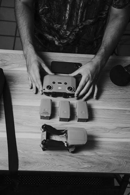
Remote Controller Components
The X Pack 7’s remote controller features a 2.4GHz 4-channel control system (Mode 2) for precise maneuvering. It also supports WiFi APP control, enabling smartphone integration for enhanced functionality. Key components include control sticks, power button, and charging port.
A dedicated camera control allows for easy photo and video capture during flight. The controller boasts a 50m range.
Battery and Charging System
The X Pack 7 utilizes a 920mAh battery, providing ample power for extended flight sessions. Charging is straightforward, requiring a compatible 7-12V power source. Always monitor the battery level during flight to prevent unexpected landings. A full charge typically takes approximately 60-90 minutes, ensuring minimal downtime. Proper battery care extends its lifespan.

Preparing for Flight
Before each flight, ensure the battery is fully charged, the remote is set up, and the drone software/app is installed and connected correctly.
Battery Charging Instructions
Utilize a 7-12V power source for optimal charging. Connect the battery to the designated charging port, observing correct polarity. A full charge typically takes between 60-90 minutes, indicated by a color change on the battery or charger.
Never overcharge the battery, as this can lead to damage or reduced lifespan. Disconnect immediately upon completion. Always monitor during the initial charge.
Remote Controller Setup
Power on the remote controller by pressing and holding the power button. Ensure fully charged batteries are installed. Download and install the dedicated app on your smartphone for enhanced control and features. Connect your smartphone to the controller via Wi-Fi, following the in-app instructions.
Calibrate the controller before first use for precise operation.
Drone Software/App Installation
Download the official X Pack 7 app from the App Store (iOS) or Google Play Store (Android). Ensure your smartphone meets the minimum system requirements for optimal performance. Grant necessary permissions, including camera and location access, during installation. Follow the on-screen prompts to create an account or log in. Update the app regularly for the latest features and bug fixes.
Flight Controls and Operation
Master precise control with the remote! Learn takeoff, landing, hovering, and advanced modes like GPS and altitude hold for a seamless experience.
Understanding the Remote Controller
The 2.4GHz remote offers a reliable 50m control range, or 25m via WiFi APP control. Familiarize yourself with each control: throttle, steering, and dedicated buttons for photo/video capture.
The 6-axis gyro ensures stable operation. Mode 2 configuration provides intuitive flight. Understand the indicator lights displaying battery level and connection status for safe, informed piloting. Proper setup is crucial for optimal performance and avoiding unexpected behavior during flight.
Basic Flight Maneuvers (Takeoff, Landing, Hovering)
To take off, gently push both control sticks down and outwards, or utilize the auto-takeoff function within the app. For landing, slowly descend using the throttle and gently touch down. Hovering is achieved by releasing the sticks; the 6-axis gyroscope and altitude hold will maintain position. Practice these maneuvers in an open area, ensuring a stable and controlled flight experience.
Advanced Flight Modes (GPS Mode, Altitude Hold)
GPS Mode utilizes satellite signals for precise positioning and return-to-home functionality, enhancing flight stability and safety. Altitude Hold maintains a consistent height, simplifying piloting and enabling smoother footage. Ensure strong GPS signal before activating GPS mode. Calibration of altitude hold is crucial for accurate performance; follow app instructions for optimal results.
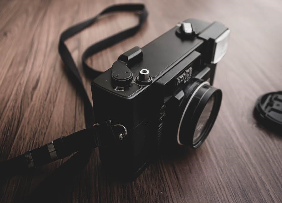
Camera and Recording Features
Capture stunning aerials! Adjust camera settings via the app for optimal photos and videos. Enjoy live streaming to your smartphone for immediate viewing.
Camera Settings and Adjustments
Fine-tune your visuals! Access camera controls through the dedicated smartphone application. Adjust resolution for detailed 2.0MP images or prioritize storage with lower settings.
Experiment with white balance to achieve accurate colors in varying lighting conditions. Explore exposure compensation to brighten or darken footage, ensuring optimal clarity.
Customize ISO levels for sensitivity in low-light scenarios, but be mindful of potential noise. Frame rate adjustments allow for smooth video or slow-motion effects.
Photo and Video Recording
Capture stunning aerials! Initiate photo capture with a single tap on the app or remote. Record videos seamlessly, monitoring remaining storage space. Utilize the drone’s stability features for clear, shake-free footage.
Experiment with different angles and compositions for creative shots. Download recordings directly to your smartphone for instant sharing. Remember to check local regulations regarding aerial photography and videography;
Live Video Feed and Smartphone Integration
Real-time viewing! Connect your smartphone to the drone’s Wi-Fi network for a live video feed. The dedicated app displays the camera’s perspective, enabling precise framing. Control drone settings and initiate recordings directly from the app interface. Enjoy seamless integration for enhanced flight experience and easy content management. Ensure a stable Wi-Fi connection for optimal performance.
Maintenance and Troubleshooting
Keep it flying! Regularly clean your X Pack 7 Drone and replace propellers as needed. This section covers common issues and provides simple solutions.
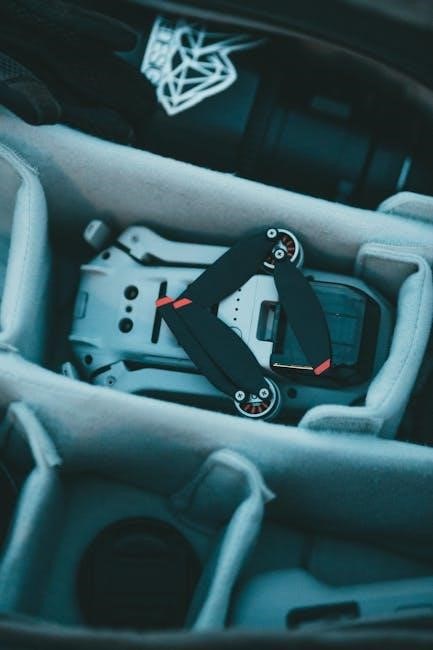
Drone Cleaning and Storage
Preserve your investment! After each flight, inspect the X Pack 7 Drone for dirt or debris. Gently wipe down the exterior with a soft, dry cloth. Avoid using liquids or harsh chemicals. Store the drone in a cool, dry place, away from direct sunlight and extreme temperatures.
Proper storage extends the lifespan of your drone and ensures optimal performance for future flights. Always disconnect the battery before long-term storage.
Propeller Replacement
Maintain optimal flight! If a propeller is damaged, replace it immediately. Ensure you use the correct propeller type (clockwise or counter-clockwise) for each motor. Gently remove the damaged propeller and securely attach the new one, ensuring it’s firmly locked in place.
Regularly inspect propellers for cracks or bends. A balanced propeller set is crucial for stable flight and prevents motor strain.
Common Issues and Solutions
Troubleshooting guide! If the drone drifts, calibrate the gyroscope. For connectivity problems, restart the app and drone. Low battery warnings indicate immediate landing is required. If propellers aren’t spinning, check connections.
Ensure sufficient charging time. If the drone loses signal, it will attempt Return-to-Home. Always prioritize safety and refer to the full manual for detailed assistance.

Safety Guidelines
Prioritize safety! Always perform pre-flight checks, adhere to flight restrictions, and understand emergency procedures. Responsible operation ensures a safe and enjoyable experience.
Pre-Flight Safety Checks
Essential pre-flight checks are crucial for safe operation. Verify propeller security, ensuring they are undamaged and firmly attached. Confirm full battery charge and adequate remote controller battery levels.
Inspect the drone’s body for any visible damage. Calibrate the compass away from metallic objects.
Ensure a clear flight path, free from obstacles and people.
Always check local regulations and airspace restrictions before each flight. A thorough inspection minimizes risks.
Flight Restrictions and Regulations
Adherence to regulations is paramount for responsible drone operation. Always comply with local laws regarding drone flight, including altitude limits and no-fly zones. Avoid flying near airports, sensitive infrastructure, or large gatherings.
Respect privacy and refrain from recording individuals without consent.
Register your drone if required by your country’s aviation authority. Stay informed about updated regulations to ensure legal and safe flights.
Emergency Procedures
In case of malfunction, initiate immediate landing procedures. If loss of control occurs, activate Return-to-Home (RTH) functionality, if available.
Be prepared to manually land the drone if RTH fails.
Avoid flying over people or property during emergencies.
Power off the drone immediately after landing to prevent further issues. Document the incident for troubleshooting and potential warranty claims.
Technical Specifications
Key specs: Dimensions are 600x600mm, weight 2500g (ATX4); Battery capacity is 920mAh, offering flight time. Camera resolution is 2.0MP.
Dimensions and Weight
Detailed measurements are crucial for transport and storage. The X Pack 7 Drone, excluding propellers, measures 600 x 600 mm in length and width. Height varies based on the ATX model – ATX4 and ATX8 both range from 350 to 550 mm.
The ATX4 model weighs approximately 2500 grams, providing a robust yet manageable flying experience.
Battery Capacity and Flight Time
Powering your adventures requires understanding the battery specifications. The X Pack 7 Drone utilizes a 920 mAh battery, designed for extended flight sessions. While precise flight time depends on conditions, expect reliable performance.
Ensure proper charging procedures, as detailed in the manual, to maximize battery life and enjoy uninterrupted aerial exploration.
Camera Resolution and Frame Rate
Capture stunning visuals with the X Pack 7 Drone’s integrated 2.0MP camera. This resolution delivers clear images and videos, perfect for aerial photography and videography. Frame rates vary depending on the selected resolution, allowing for smooth motion capture.
Optimize settings for desired results, ensuring vibrant and detailed content every time you fly.
Understanding the 6-Axis Gyroscope
The 6-axis gyroscope ensures stable flight by detecting and correcting rotational movements, providing exceptional control and smooth aerial footage.
How the Gyroscope Stabilizes Flight
The X Pack 7’s 6-axis gyroscope utilizes three gyroscopes measuring angular velocity around the roll, pitch, and yaw axes. Combined with three accelerometers, it detects linear acceleration. This data is processed by the flight controller, which instantly adjusts motor speeds.
These adjustments counteract unwanted rotations, maintaining a stable and level flight path, even in windy conditions. The gyroscope’s rapid response ensures precise control and smooth, cinematic footage, enhancing the overall flying experience and image quality.
Troubleshooting Gyroscope Issues
If the X Pack 7 exhibits erratic flight, or fails calibration, suspect gyroscope problems. First, ensure propellers are securely attached and undamaged. Recalibrate the gyroscope following the manual’s instructions – a level surface is crucial.
Check for magnetic interference from nearby metal objects or power lines. If issues persist, reset the flight controller. Contact customer support if recalibration and resets don’t resolve the instability, as internal component failure may be present.
Altitude Hold Function Explained
Altitude Hold maintains a consistent flight height, simplifying operation. The 6-axis gyroscope works with the barometer to achieve stable, hands-free hovering.
Benefits of Altitude Hold
Altitude Hold significantly simplifies drone operation, particularly for novice pilots. It eliminates the constant need to adjust the throttle, allowing for smoother, more stable aerial footage and photography. This feature is crucial for capturing consistent shots and reduces pilot fatigue during extended flights.
Combined with the 6-axis gyroscope, Altitude Hold ensures the X Pack 7 maintains a fixed altitude, even in mild wind conditions, resulting in professional-quality results with minimal effort.
Calibration of Altitude Hold
Proper calibration is essential for accurate Altitude Hold performance. Begin on a level surface, ensuring the drone is stationary. Access the drone’s app and navigate to the calibration settings. Follow the on-screen prompts, which typically involve briefly taking off and landing.
Recalibrate if experiencing drift or inconsistent altitude maintenance. Regular calibration, especially after transport or significant temperature changes, optimizes the 6-axis gyroscope and ensures reliable altitude control for the X Pack 7.

Wi-Fi and App Control Details
Connect to the drone’s Wi-Fi network via your smartphone. The app unlocks features like live video feed, camera settings, and intelligent flight modes for the X Pack 7.
Connecting to the Drone’s Wi-Fi
To connect, power on the X Pack 7 drone and your smartphone. Navigate to your phone’s Wi-Fi settings and locate the drone’s network – typically labeled “X-Pack7-WiFi”. Select it and enter the default password (often “12345678” or found in the manual).
Once connected, open the dedicated drone app;
A successful connection enables live video streaming and remote control functionality, allowing for seamless operation and access to advanced features.
App Features and Functionality
The X Pack 7 app provides comprehensive control and monitoring. Features include a live video feed, adjustable camera settings, intelligent flight modes (GPS, Altitude Hold), and flight data telemetry. Users can access photo/video recording controls, map views, and drone status information.
The app also facilitates firmware updates and offers customizable settings for a personalized flying experience, enhancing overall usability.
Power Supply Information (7-12V)
The X Pack 7 operates efficiently within a 7-12V power range, offering flexibility. Use a stable power source for optimal performance and longevity.
Recommended Power Sources
For reliable operation of your X Pack 7 Drone, we recommend utilizing a regulated DC power supply delivering a consistent 7-12V output. Avoid unstable or fluctuating power sources, as these can negatively impact flight performance and potentially damage internal components.
A quality USB power adapter, meeting the specified voltage range, is suitable for charging. Ensure the adapter provides sufficient amperage for efficient charging times. Prioritize safety and always verify compatibility before connecting any power source.
Voltage Considerations
Maintaining proper voltage is crucial for the X Pack 7 Drone’s longevity and performance. Operating outside the 7-12V range risks component damage or reduced flight time. Lower voltages may lead to insufficient power, while exceeding 12V could cause irreversible harm. Always double-check your power supply’s output before connecting it to the drone. Consistent voltage ensures optimal functionality and safe operation during every flight.
Decal and Kit Information (Lockheed X-7 Reference)
This kit includes 53 resin parts and a display dolly, referencing the Lockheed X-7. Model dimensions are 600 x 600 mm, excluding propellers;
Resin Parts and Display Dolly
The kit boasts a comprehensive collection of 53 meticulously crafted resin parts, designed to enhance the display potential of your X Pack 7 Drone model. These high-quality components allow for detailed customization and accurate representation.
Included is a dedicated display dolly, providing a stable and aesthetically pleasing platform for showcasing your completed model. This dolly ensures secure positioning and facilitates easy viewing, elevating the overall presentation of your X-7 inspired drone replica.
Model Dimensions (600 x 600 mm)
The Lockheed X-7 inspired model, excluding propellers, measures 600 x 600 millimeters, offering a substantial and impressive display piece. Height adjustments are available, ranging from 350 to 550 millimeters for both ATX4 and ATX8 configurations. Weighing approximately 2500 grams, the model provides a realistic feel and presence. These dimensions ensure compatibility with various display spaces, allowing for a striking visual representation of this iconic aircraft.
UAV Advantages and Comparative Studies
Drones offer significant benefits over traditional methods, including cost-effectiveness, enhanced safety, and access to difficult-to-reach areas for data collection.
Benefits of Using Drones
Employing the X Pack 7 Drone delivers numerous advantages. Its aerial perspective provides unique viewpoints for photography and videography, surpassing ground-based methods. Drones enhance efficiency in inspections, reducing time and labor costs.
They access hazardous environments safely, minimizing risk to personnel. Furthermore, drones gather data quickly, offering real-time insights for informed decision-making, ultimately boosting productivity and safety.
Comparison to Traditional Methods
Compared to conventional techniques, the X Pack 7 Drone offers significant improvements. Traditional inspections often require scaffolding or manned aircraft – costly and time-consuming. The drone’s agility and lower operational expenses provide a compelling alternative. Data collection is faster and more precise, reducing errors.
Its compact size enables access to confined spaces, exceeding the capabilities of traditional methods, enhancing overall efficiency.